Document Reference: TN201009001 - Rev: 4.14 - Last Update: 14-11-2020 02:38 GMT - Downloaded: 27-Apr-2024 19:41 GMT
A NOT gate (aka inverter) is a logic gate with only one input and one output. The output state is always the opposite of the input state.
NOT Gate (Inverter) Symbols
The input (A) of a NOT gate is on the left, and the output (X) is on the right of the logic NOT gate symbol.
| Distinctive Shape | Rectangular Shape | DIN Shape (Historic) |
|---|---|---|
 |  |  |
NOT Gate Truth Table
Truth Table for NOT Gate
A | X |
|---|---|
0 | 1 |
1 | 0 |
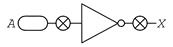
NOT Gate Test-It
To test the gate, click the switch symbol in the image below.


NOT Gate Logical Expressions
Word Equation
X = NOT A
Boolean Algebra
In boolean algebra the overbar sign ( ) stands for the NOT operation, e.g.:
X = A
Alternative notations: X = ∼A or X = ¬A
A | X = A |
|---|---|
0 | X = 1 |
1 | X = 0 |