Document Reference: TN201009003 - Rev: 4.14 - Last Update: 14-11-2020 03:42 GMT - Downloaded: 28-Apr-2024 09:27 GMT
A OR gate is a logic gate with two or more inputs and one output. One or more input states must be high to produce a high output.
OR Gate Symbols
The inputs (A, B) of an OR gate are on the left, and the output (X) is on the right of the logic OR gate symbol.
| Distinctive Shape | Rectangular Shape | DIN Shape (Historic) |
|---|---|---|
 |  |  |
OR Gate Truth Tables
Truth Table for OR Gate with 2 Inputs
A | B | X |
|---|---|---|
0 | 0 | 0 |
0 | 1 | 1 |
1 | 0 | 1 |
1 | 1 | 1 |
Truth Table for OR Gate with 3 Inputs
A | B | C | X |
|---|---|---|---|
0 | 0 | 0 | 0 |
0 | 0 | 1 | 1 |
0 | 1 | 0 | 1 |
0 | 1 | 1 | 1 |
1 | 0 | 0 | 1 |
1 | 0 | 1 | 1 |
1 | 1 | 0 | 1 |
1 | 1 | 1 | 1 |
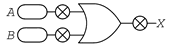
OR Gate Test-It
To test the gate, click the switch symbols in the image below.


OR Gate Logical Expressions
Word Equation
X = A OR B
Boolean Algebra
In boolean algebra the plus sign (+) stands for the OR operation, e.g.:
X = A + B
Alternative notation: X = A ∨ B
A | B | X = A + B |
|---|---|---|
0 | 0 | X = 0 + 0 = 0 |
0 | 1 | X = 0 + 1 = 1 |
1 | 0 | X = 1 + 0 = 1 |
1 | 1 | X = 1 + 1 = 1 |
A | B | C | X = A + B + C |
|---|---|---|---|
0 | 0 | 0 | X = 0 + 0 + 0 = 0 |
0 | 0 | 1 | X = 0 + 0 + 1 = 1 |
0 | 1 | 0 | X = 0 + 1 + 0 = 1 |
0 | 1 | 1 | X = 0 + 1 + 1 = 1 |
1 | 0 | 0 | X = 1 + 0 + 0 = 1 |
1 | 0 | 1 | X = 1 + 0 + 1 = 1 |
1 | 1 | 0 | X = 1 + 1 + 0 = 1 |
1 | 1 | 1 | X = 1 + 1 + 1 = 1 |