A AND gate is a logic gate with two or more inputs and one output. All input states must be high to produce a high output.
AND Gate Symbols
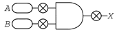
The inputs (A, B) of an AND gate are on the left, and the output (X) is on the right of the logic AND gate symbol.
| Distinctive Shape | Rectangular Shape | DIN Shape (Historic) |
|---|---|---|
 |  |  |
AND Gate Truth Tables
Truth Table for AND Gate with 2 Inputs
A | B | X |
|---|---|---|
0 | 0 | 0 |
0 | 1 | 0 |
1 | 0 | 0 |
1 | 1 | 1 |
Truth Table for AND Gate with 3 Inputs
A | B | C | X |
|---|---|---|---|
0 | 0 | 0 | 0 |
0 | 0 | 1 | 0 |
0 | 1 | 0 | 0 |
0 | 1 | 1 | 0 |
1 | 0 | 0 | 0 |
1 | 0 | 1 | 0 |
1 | 1 | 0 | 0 |
1 | 1 | 1 | 1 |
AND Gate Test-It
To test the gate, click the switch symbols in the image below.


AND Gate Logical Expressions
Word Equation
X = A AND B
Boolean Algebra
In boolean algebra the multiplication sign (⋅) stands for the AND operation, e.g.:
X = A ⋅ B or simplified: X = AB
Alternative notations: X = A ∧ B or X = A & B
A | B | X = AB |
|---|---|---|
0 | 0 | X = 0 ⋅ 0 = 0 |
0 | 1 | X = 0 ⋅ 1 = 0 |
1 | 0 | X = 1 ⋅ 0 = 0 |
1 | 1 | X = 1 ⋅ 1 = 1 |
A | B | C | X = ABC |
|---|---|---|---|
0 | 0 | 0 | X = 0 ⋅ 0 ⋅ 0 = 0 |
0 | 0 | 1 | X = 0 ⋅ 0 ⋅ 1 = 0 |
0 | 1 | 0 | X = 0 ⋅ 1 ⋅ 0 = 0 |
0 | 1 | 1 | X = 0 ⋅ 1 ⋅ 1 = 0 |
1 | 0 | 0 | X = 1 ⋅ 0 ⋅ 0 = 0 |
1 | 0 | 1 | X = 1 ⋅ 0 ⋅ 1 = 0 |
1 | 1 | 0 | X = 1 ⋅ 1 ⋅ 0 = 0 |
1 | 1 | 1 | X = 1 ⋅ 1 ⋅ 1 = 1 |
AND Gate Circuit with Two Relays
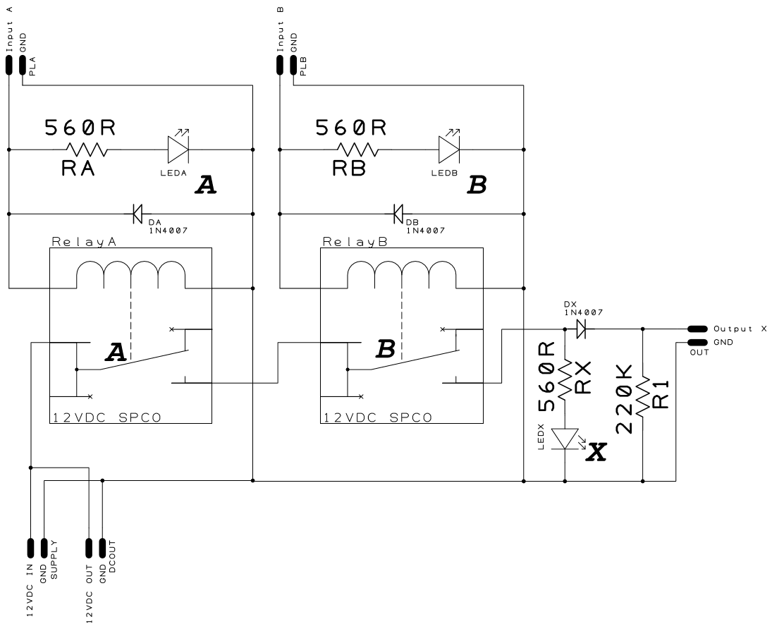
By default, and without a signal on Input A and Input B, the Output X will be pulled to LOW (0) via R1.
A 12VDC (1/HIGH) signal on terminal Input A will light LEDA and energize RelayA. Energizing RelayA will allow 12VDC to pass via switched contact A from the terminal 12VDC IN to switched contact B.
A 12VDC (1/HIGH) signal on terminal Input B will light LEDB and energize RelayB. Energizing RelayB will allow 12VDC to pass via switched contact B and via DX from the switched contact A to the terminal Output X.
LEDX will light and Output X will be HIGH as soon as 12VDC is allowed to pass via switched contacts A and B.